
A vehicle network diagnostics guide starts with one hard truth: a fault code is not a diagnosis. On a modern vehicle, one damaged wire, low supply voltage or missing module can trigger warnings in systems that are nowhere near the original fault. The engine may crank but not start, the ABS light may appear alongside steering errors, or a scan tool may report that half the vehicle is unavailable. Guessing at replacement parts is expensive. Testing the network properly is faster.
For workshops, mobile technicians and capable DIY users, the objective is simple: establish whether the vehicle’s control units can communicate, identify where that communication fails, and prove the repair before handing the keys back.
What a vehicle network actually does
Modern vehicles use electronic control units, or ECUs, to manage systems including engine operation, braking, airbags, body electrics, steering, climate control and infotainment. Rather than each module having a dedicated wire to every other module, most share data across a communication network.
CAN bus is the network you will encounter most often. It normally uses two twisted wires, CAN High and CAN Low, to carry messages between modules at high speed while resisting electrical interference. Many vehicles also use LIN for simpler local functions such as mirrors, seat controls and window motors. Newer platforms may include FlexRay or automotive Ethernet, particularly where driver-assistance systems and high data rates are involved.
That layout makes vehicles more capable, but it changes the diagnostic process. A communication code does not automatically mean the module named in the code has failed. It may have lost power, ground, network connection or a gateway route. Equally, a module that has failed internally can pull down a network shared by several healthy units.
Start with the vehicle’s overall condition
Network diagnosis begins before the scan tool is connected. A weak battery can create a long list of misleading low-voltage and communication faults, especially after repeated start attempts. Check battery state, cranking voltage and charging performance first. On vehicles with battery monitoring systems, confirm the battery is correctly specified and registered where required.
Then look for the obvious workshop causes. Check relevant fuses under load, not merely by sight. Inspect earth points for corrosion or looseness, particularly around battery trays, wheel arches and under-bonnet fuse boxes. Water ingress is a frequent cause of network faults, so examine footwells, bulkhead areas, luggage compartments and known module locations for dampness, green corrosion or previous repair work.
Ask what happened before the fault appeared. A flat battery, jump start, accident repair, windscreen replacement, aftermarket alarm installation or rodent damage can narrow the search dramatically. A network problem often has a physical cause, and the vehicle history points towards it.
Scan every available module, not just the engine
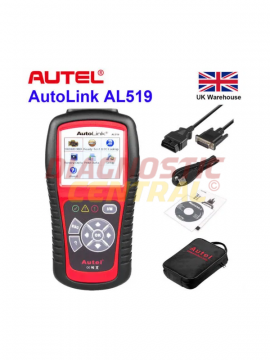
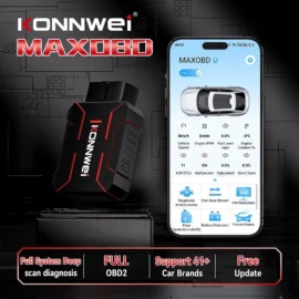
A basic OBD2 reader is useful for engine and emissions-related codes, but it may only see a fraction of the vehicle. Proper network diagnosis needs a scanner with broad system coverage and, where necessary, brand-specific capability. Read the full vehicle, save the initial report and note which control units respond.
The pattern matters more than a single U-code. If every module except the engine ECU communicates, investigate the engine ECU’s supplies, grounds and network connection. If a cluster of modules on one side of the vehicle is absent, look for a shared fuse, earth, gateway branch or harness section. If the diagnostic gateway itself is inaccessible, start at the diagnostic socket, its power and grounds, then work towards the gateway.
Record whether faults are current, stored or intermittent. Clear nothing until the original scan has been saved. Clearing codes too early removes useful evidence and can make an intermittent issue harder to reproduce. After repairs, a fresh full scan gives a clear before-and-after result.
Understand the difference between a code and a symptom
Codes such as “lost communication with control module” identify a reporting module’s complaint. They do not prove why the other module is missing. The cause could be no ignition feed, poor earth, a broken CAN wire, a short circuit, incorrect coding after replacement, or an internal module fault.
Use live data and module identification to add context. A module that responds but reports implausible voltage may have a supply problem. A replacement unit that communicates but will not operate may require coding, parameterisation or security access. This is why compatibility and vehicle-specific functions matter when selecting diagnostic equipment.
Test CAN bus methodically
Once the scan pattern suggests a network issue, use electrical tests to confirm it. Always consult accurate wiring information for the vehicle in front of you. Connector layouts, gateway positions and network design vary widely between manufacturers and model years.
With the vehicle powered down and allowed to enter sleep mode, resistance measured between CAN High and CAN Low at an appropriate point is commonly around 60 ohms on a conventional two-terminator high-speed CAN network. That reading comes from two 120-ohm terminating resistors connected in parallel. Around 120 ohms may indicate one terminator or one side of the network is missing. A very low reading can suggest a short or additional unwanted load. An open circuit points towards a break, disconnected section or incorrect test point.
Those figures are a guide, not a substitute for the wiring diagram. Some vehicle architectures use multiple segments, gateways or different termination arrangements. Never force a conclusion from one resistance reading alone.
With the system awake, a multimeter can identify a supply short or a line pinned high or low, but an oscilloscope is the stronger tool for assessing actual CAN traffic. A healthy high-speed CAN signal shows opposing activity on the two lines. Noise, distorted waveforms, missing dominant states or irregular voltage levels can expose poor connections and electrical interference that a resistance check misses.
Avoid probing at random with unsuitable pins. Back-probe carefully, use the correct breakout leads where possible, and do not bridge terminals. One slip can create a new fault and complicate the original repair.
Isolate the fault without creating more work
If the network is shorted or no modules communicate, isolate sections according to the wiring diagram. Disconnecting suspect modules one at a time can reveal the component that is pulling the bus down, but it must be done with the correct ignition state and safe disconnection procedure. Airbag, steering lock, immobiliser and high-voltage systems require particular caution.
Start with modules exposed to water, accident damage or recent work. Do not condemn a costly ECU simply because disconnecting it restores communication. Check its power feeds, grounds and connector pins first. A corroded supply terminal can make a healthy ECU appear dead; a harness short can make a healthy ECU appear guilty.
For intermittent faults, carry out a controlled wiggle test while monitoring network status or the scope trace. Move one harness area at a time and watch for the fault to return. This takes patience, but it is more defensible than replacing parts based on possibility.
Choose tools that match the job
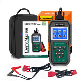
Tool choice depends on the vehicle range and depth of work. For servicing and common warning lights, a dependable multibrand scanner with full-system access, live data and service functions may be enough. Independent garages working across several makes benefit from a platform that can perform active tests, coding functions where supported and detailed fault reporting.
For network electrical work, add a quality multimeter, a battery tester, suitable back-probing leads and access to accurate wiring data. An oscilloscope becomes worthwhile when network faults, sensor signals and intermittent electrical problems are regular workshop work rather than occasional jobs. Commercial vehicle technicians should also ensure their equipment and adapter leads cover the relevant lorry and trailer diagnostic sockets.
The cheapest scanner is not always the lowest-cost option. Limited module coverage can send a technician down the wrong path, while poor update support soon becomes a problem as vehicle platforms change. Buy for the vehicles you actually see, the functions you need and the level of support required when a difficult job arrives.
Verify the repair under real conditions
A successful repair is more than a cleared dashboard light. Reconnect everything correctly, clear faults only after recording them, and perform a full vehicle scan again. Confirm that all expected modules respond, no current communication codes return and live data is plausible.
Then cycle the ignition, start the vehicle and road-test it where safe and appropriate. Some faults only appear when voltage changes, a module wakes from sleep or the vehicle reaches a certain speed. If coding, calibration or an initialisation routine is required after the repair, complete it and check for faults once more.
Good network diagnostics is disciplined electrical work backed by the right scan data. Test power and ground, understand the communication pattern, prove the wiring and verify the result. That approach turns a confusing page of U-codes into a repair you can stand behind.