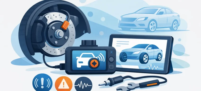
An ABS warning light is not a licence to fit a wheel-speed sensor and hope for the best. On modern vehicles, the sensor, its wiring, the wheel bearing encoder ring, the reluctor ring and the ABS control unit all contribute to the same fault. Knowing how to diagnose ABS sensors properly prevents wasted parts, repeat repairs and a vehicle returning with the warning lamp still on.
The most efficient approach combines a capable scan tool with a physical inspection and a targeted electrical test. Start with evidence, not assumptions.
What an ABS sensor fault really means
The ABS system monitors individual wheel speeds. When it detects a wheel beginning to lock under braking, it rapidly controls brake pressure to help maintain steering control. The same wheel-speed signals are often used by traction control, stability control, hill-hold systems, speedometers and automatic gearboxes.
That is why an ABS fault may bring up several warning lights at once. A car may show ABS, traction control and stability control warnings, while a van or lorry may also log related chassis-system faults. The underlying problem can still be one poor wheel-speed signal.
A diagnostic trouble code such as “front left wheel-speed sensor circuit” narrows the search area, but does not prove the sensor itself has failed. It can indicate an open circuit, short circuit, damaged connector, excessive air gap, contaminated sensor face or a distorted signal from the magnetic encoder built into the wheel bearing.
The tools needed to diagnose ABS sensors
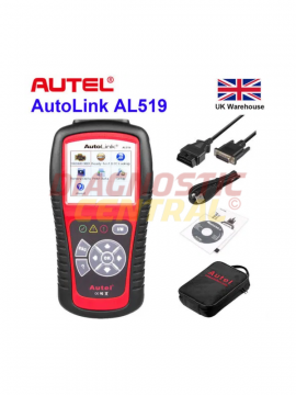
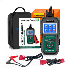
A basic code reader can identify that the ABS module has stored a fault, but it may not access the live wheel-speed data needed to confirm the cause. Use a scanner that communicates with the vehicle’s ABS or brake control module, rather than one limited to engine fault codes.
For a reliable diagnosis, have a suitable diagnostic scanner, a digital multimeter, back-probe leads and basic hand tools available. An oscilloscope is particularly useful for intermittent faults and for comparing sensor waveforms, although it is not essential for every job. A wiring diagram or trusted repair information is also valuable because sensor designs and pinouts vary widely between manufacturers.
Do not pierce insulation with probes unless there is no proper alternative. It creates a future corrosion point, especially around wheel arches where water and road salt are constant.
How to diagnose ABS sensors step by step
Read ABS codes before touching the vehicle
Connect the scanner and enter the ABS, brake or chassis module. Record every stored and pending code, including manufacturer-specific descriptions and freeze-frame information where available. Do this before clearing anything.
Pay attention to whether the code identifies a circuit fault or an implausible signal. “Open circuit” or “short to ground” usually points towards wiring, terminals or the sensor’s internal electronics. “Signal erratic”, “mechanical fault” or “implausible wheel speed” can point to the sensor, air gap, reluctor ring or wheel bearing encoder.
Also check the battery voltage. Low system voltage can trigger misleading module faults, particularly after a weak battery, jump start or charging-system issue. If several unrelated control units have communication codes, resolve the supply-voltage problem before condemning an ABS component.
Inspect the wheel-end components closely
Locate the sensor and follow its lead from the hub to its connector. Look for chafing where the loom moves with the steering or suspension, crushed cable clips, split outer insulation and signs of impact damage. Front sensor wiring often fails near the strut or where the harness flexes during steering. Rear wiring can suffer from corrosion, damaged routing or water entering connectors.
Disconnect the connector only after checking its condition externally. Inspect for green corrosion, spread terminals, water ingress and a connector that does not lock firmly. Clean or repair terminals correctly rather than spraying contact cleaner into a badly corroded plug and calling it fixed.
If accessible, remove the sensor and inspect its tip. Metal debris can build up on some inductive sensors and weaken the signal. Do not force a seized sensor out of an alloy hub: it is easy to turn a diagnostic job into a hub replacement. Check the sensor seating point for corrosion that may push the sensor away from the tone ring and create an excessive air gap.
Check live wheel-speed data
Live data is usually the quickest confirmation test. Raise the vehicle safely where appropriate, following proper lifting procedures, and rotate each wheel by hand while monitoring individual wheel speeds. On some vehicles, a short controlled road test is more effective because the module will not report low-speed data accurately while stationary.
Compare all four readings. The suspect wheel may show zero speed, drop out intermittently, react later than the others or report a speed that clearly differs from the remaining wheels. A fault that appears only at a particular speed is especially revealing. For example, a wheel reading that disappears at walking pace but returns above 10 mph can indicate a damaged encoder ring or a poor sensor gap rather than a dead sensor.
Bear in mind that tyre sizes, differential action and wheel lift can affect readings. Compare like for like and focus on a repeatable abnormal pattern, not tiny variations.
Identify the sensor type before testing it
There are two common ABS sensor designs. Older passive inductive sensors generally have two wires and generate an AC voltage as the wheel turns. Many newer vehicles use active Hall-effect or magnetoresistive sensors, often with two or three wires, supplied by the ABS module.
This distinction matters. A resistance test can be useful on a passive sensor, but it is often meaningless on an active sensor and may lead to a false diagnosis. Never use an arbitrary resistance figure found online as proof that a sensor is good or bad. Check manufacturer data where possible, then compare readings against the sensor on the opposite side of the same axle.
Test the circuit, not just the sensor
For a passive sensor, disconnect it and measure resistance across its terminals. An open circuit or direct short is a strong indication of failure. If its resistance is plausible, switch the multimeter to AC volts and rotate the wheel. The sensor should generate a rising alternating signal as wheel speed increases. Compare it with the opposite wheel under the same conditions.
For an active sensor, check the supply and ground at the vehicle-side connector with the ignition on, using the correct wiring information. Depending on the system, the module may provide a voltage supply, current-modulated circuit or digital signal arrangement. Confirm power, ground integrity and continuity between the connector and ABS module before replacing the sensor.
A voltage-drop test is better than a simple continuity test when a wiring fault is suspected. A wire can show continuity on a meter yet fail under load because corrosion has increased its resistance. Flex the harness gently during testing. If readings change or the live data drops out, you have found a likely intermittent break.
Check the reluctor ring or magnetic encoder
A new sensor cannot compensate for a damaged trigger surface. Older systems may use a visible toothed reluctor ring on the CV joint, hub or driveshaft. Look for cracked teeth, heavy rust expansion, missing sections and damage caused by previous work.
Many later vehicles use a magnetic encoder ring integrated into the wheel bearing seal. It may not be visible, and it can be fitted on the wrong side if the bearing has been installed incorrectly. A weakened, contaminated or damaged magnetic strip produces an uneven signal that can mimic sensor failure. An oscilloscope gives the clearest answer, but live data and a comparison with the opposite wheel often reveal the issue.
If the fault began shortly after a wheel bearing, CV joint, suspension or brake repair, treat installation error as a serious possibility. Check bearing orientation, sensor seating, hub cleanliness and cable routing before ordering parts.
Clear codes and prove the repair
After repairing the confirmed fault, clear the ABS codes and recheck the module. Then carry out a safe road test while monitoring live wheel speeds if your scanner allows it. Confirm that all wheels track consistently, the warning lamps remain off and no code returns.
Do not test ABS operation by deliberately braking hard on public roads. A normal drive that includes low-speed turns, steady acceleration and controlled braking is enough to confirm most wheel-speed repairs. Some vehicles require a short drive cycle before the warning lamp extinguishes.
If a code returns immediately after clearing, revisit the circuit tests and module connector rather than fitting another sensor. If it returns only after driving, concentrate on signal quality, bearing encoders and harness movement.
A dependable scanner turns ABS diagnosis from educated guesswork into a measured repair process. Diagnostic Central equipment is designed for the workshop reality of reading manufacturer-level faults and live data quickly, but the tool is only as useful as the method behind it. Test the signal, inspect the mechanical trigger and verify the repair on the road – that is how wheel-speed faults get fixed once, not twice.