A trailer ABS warning lamp can turn a straightforward collection into a roadside delay, an inspection issue, or a customer vehicle sitting in the yard. This trailer ABS diagnostics guide is built for the point where guesswork stops: establish whether the fault is in the tractor unit, the trailer supply, the wiring, a wheel-end sensor or the ABS electronic control unit (ECU), then prove the repair before the trailer leaves.
Trailer ABS is not a system to diagnose by fitting parts until the lamp disappears. The warning may be caused by a damaged sensor lead, but it can also result from low supply voltage, corrosion in a connector, a poor earth, a failed modulator circuit or a communication problem. A compatible commercial diagnostic tool and the correct trailer lead shorten that process considerably.
Start with the warning lamp and fault conditions
First, confirm exactly when the warning is present. On a correctly connected combination, the trailer ABS warning indication should illuminate during the initial lamp check and then extinguish when the system has completed its checks and receives the required wheel-speed information. A lamp that stays on before moving points you in a different direction from one that returns only after a few metres.
Ask the driver what changed before the fault appeared. A lamp after a wheel bearing repair, brake overhaul or tyre replacement often directs attention to sensor position, sensor damage or the exciter ring. A fault that appears only with one tractor unit may be a supply or socket issue rather than a trailer defect. Intermittent warnings after rain or jet washing make water ingress and connector condition prime suspects.
Do not assume the dashboard indication tells the full story. The ABS ECU may store active, intermittent and historic fault codes. Read and record them before clearing anything. Clearing codes at the start removes useful evidence, particularly when the issue is intermittent.
Trailer ABS diagnostics guide: check supply before sensors
The fastest technicians start at the connection point. A trailer ECU cannot provide reliable sensor readings or modulator control without a stable electrical supply and earth. Inspect the plug, socket and cable for bent pins, pushed-back terminals, green corrosion, heat damage, loose strain relief and previous repairs hidden under tape.
Use a multimeter to verify the relevant permanent and switched supplies, along with earth integrity, at the trailer connector and again at the ECU connector where access allows. A voltage reading that looks acceptable with no load can collapse when the system wakes up. Voltage-drop testing is more useful than simply checking continuity on suspect power and earth circuits.
The exact pin allocation and operating arrangement depend on the trailer, its age and the ABS installation. Work from the correct wiring information for that unit rather than relying on a generic pin-out. Trailer systems may be supplied by manufacturers such as WABCO, Knorr-Bremse or Haldex, and connector layouts, diagnostic access and fault descriptions can differ.
If the fault follows the trailer when connected to another known-good tractor, focus on the trailer. If a known-good trailer shows the same warning behind one tractor, inspect the tractor socket, supply circuit and earth path before dismantling the trailer.
Connect a tool that can see the trailer ECU
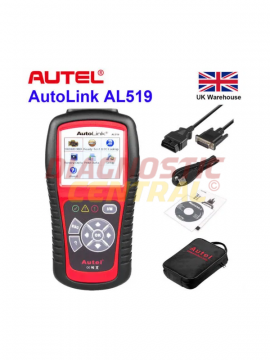
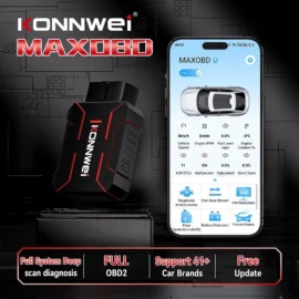
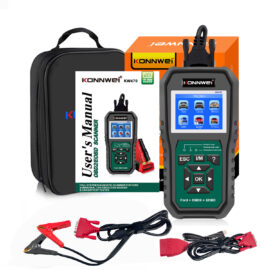
A basic car code reader is not a trailer ABS diagnostic solution. The tool must support the relevant commercial protocol and ECU, while the adapter cable must physically suit the trailer diagnostic socket. This is where coverage matters: the right interface can identify the ECU, retrieve manufacturer-specific codes, show live wheel-speed data and, on supported systems, operate component tests.
Before connecting, check battery condition and maintain supply voltage where necessary. Low voltage can create misleading communication and ECU faults. With the ignition and system state set according to the equipment instructions, identify the ECU and save the initial scan. Record the ECU part number, software details where available, fault code, status and frequency count.
Fault text is a direction, not a diagnosis. A code for a wheel-speed sensor circuit does not automatically condemn the sensor. It may indicate an open circuit, short to earth, short to supply, excessive air gap, damaged cabling or an issue inside the ECU. The live data and physical checks determine which.
Test wheel-speed sensors at the wheel end
Wheel-speed sensor faults are common because the components live in a harsh environment. Cables flex with suspension movement, road debris strikes the sensor lead, and corrosion develops around the hub and connector. Start with a close inspection from sensor to chassis harness. Look for crushed cable, chafing, stretched wiring, insecure clips and corrosion at intermediate connectors.
Check the sensor mounting and its relationship with the exciter ring. Depending on the design, a sensor that is not correctly seated can produce a weak or inconsistent signal. Wheel bearing movement, contamination, a cracked or damaged ring, and metal debris around the sensor can all affect the reading. Do not force a sensor out of a corroded carrier without considering that the carrier may need replacement as part of a proper repair.
Resistance checks can identify obvious open or short circuits on passive sensor types, but they are not the whole test. Compare results across matching axles where practical and use the manufacturer specification. For a stronger diagnosis, monitor live wheel-speed data while turning each wheel safely, or use a scope where the fault is intermittent and the equipment is available. A sensor that passes a static resistance test can still fail under vibration or produce a poor signal at low speed.
After replacement or adjustment, route and secure the cable exactly as intended. A new sensor lead left loose near moving suspension or a tyre will soon return as the next fault.
Do not overlook modulators, wiring and ECU faults
When sensor data is credible but the ECU reports a modulator or valve fault, move methodically through the circuit. Check the connector for water ingress and terminal tension, then test the wiring between ECU and modulator for continuity, shorts and voltage drop. A visual inspection alone is not enough on a loom that has been repaired several times.
Where the diagnostic tool supports actuator tests, command the relevant modulator only when the trailer is secured and the test can be carried out safely. Listen for operation, but do not treat an audible click as complete proof. Electrical operation, air supply, valve condition and the pneumatic side all need to be considered. A valve may energise yet still have a mechanical or air-flow problem.
ECUs are less common failure points than wiring and wheel-end components, but they should not be ruled out. Condensation inside the ECU housing, damaged pins, reversed-polarity events and poor supply connections can all create ECU-related codes. Replace an ECU only after proving the feeds, earths, harness and connected components. If coding or parameterisation is required, use the correct procedure and verify the configuration for the trailer.
Clear codes only after the repair is proven
Once the physical repair is complete, clear the fault memory and run the system through its checks again. Re-read the ECU before road testing. If the code returns immediately, the fault is still present or the repair has introduced a connection issue. If it returns only once the wheels rotate, revisit sensor signal quality and the conditions recorded in the fault data.
A controlled road test is the final confirmation, subject to site safety and normal workshop procedures. Confirm the warning indication behaves correctly and that live wheel speeds are plausible across the monitored wheels. Do not release the trailer simply because a lamp has gone out in the bay.
For workshops handling mixed fleets, keep a record of common connector faults, repeat axle positions and recurring trailer defects. It improves first-time fix rates and helps identify whether a problem is isolated or linked to a particular fleet, route or maintenance practice. Diagnostic Central equipment is selected around that practical requirement: compatible coverage, clear fault information and tools that earn their place in the workshop.
The best trailer ABS repair is the one supported by evidence – a stable supply, a sound circuit, credible live data and a fault-free verification test. That approach protects time, parts margin and, more importantly, the safe operation of the trailer on the road.