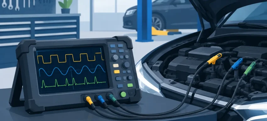
A fault code can point to a circuit, but it cannot show whether a signal is weak, distorted, intermittent or missing under load. That is where an automotive oscilloscope setup guide earns its place in the workshop. Set up correctly, a scope lets you see what the ECU, sensor, actuator or network is actually doing – often before parts are ordered on guesswork.
Quick answer
- Start with the correct probe and connection method for the circuit, not the default leads for every test.
- Set voltage range, timebase and trigger before judging a waveform.
- Connect the earth lead only where it is safe to do so, particularly around ignition and mains-powered equipment.
- Capture the fault under the conditions in which it occurs: cranking, hot idle, load or a road test where appropriate.
- Save known-good traces alongside vehicle details so future comparisons are faster and more reliable.
Start with the question, not the scope settings
An oscilloscope is most useful when the test has a clear purpose. “Check the crank sensor” is too broad. A better question is: does the crankshaft position sensor produce a clean signal while cranking, and does the ECU receive it? That question determines where to connect, which channel to use, the voltage range and the time window required.
Before connecting anything, confirm the vehicle system and signal type. A two-wire inductive crank sensor, three-wire Hall sensor, injector control circuit and CAN bus all need different approaches. Check wiring information where available and identify the component ground, supply and signal wires. Wire colours alone are not enough, especially on repaired vehicles or complex looms.
A scan tool remains a valuable first step. Read stored and pending faults, inspect live data, and use bidirectional functions where supported. Then use the scope to verify what the scan data cannot prove. For example, a live-data RPM reading during cranking does not automatically confirm that the crank waveform is healthy, correctly timed or free from interference.
Choose probes that suit the circuit
Standard 10:1 voltage probes are the everyday choice for low-voltage sensor signals, actuator feeds and network diagnostics. The 10:1 setting reduces the voltage reaching the scope input and provides useful protection, but the scope must also be set to match the probe attenuation. If the probe says 10:1 and the channel is set to 1:1, every displayed voltage value will be wrong by a factor of ten.
For current testing, use an automotive current clamp rather than breaking the circuit. It is particularly useful for injector current ramps, fuel-pump draw, starter current and relative compression testing. Zero the clamp before use and make sure the jaw is fully closed. Even a small offset can make a low-current reading misleading.
Ignition testing needs dedicated equipment. A capacitive secondary pickup can show secondary ignition patterns without directly connecting to high voltage. For primary ignition, use an appropriately rated attenuator or ignition probe where required by the scope manufacturer. Do not put a standard low-voltage probe directly onto a coil-on-plug secondary circuit.
Back-probing pins is often cleaner than piercing wires, but it still demands care. Use suitable back-probes, support the lead so it cannot pull loose, and avoid spreading terminal contacts. Piercing probes can be useful on older wiring, but seal any puncture properly afterwards to prevent corrosion.
Automotive oscilloscope setup: the core controls
The three controls that decide whether a waveform is usable are voltage scale, timebase and trigger. They work together. A perfect sensor signal can look like a flat line if the voltage range is too large, while an excellent ignition event can disappear if the capture window is too short.
Set the voltage scale first
Begin with a range comfortably above the expected voltage, then reduce it until the signal occupies a useful portion of the screen without clipping. A 0-5 V Hall-effect signal might begin at 5 V or 10 V per division depending on the scope, while a charging-system ripple test needs a much lower scale to reveal small AC fluctuations on top of battery voltage.
Use DC coupling when both the signal voltage and its changing pattern matter. AC coupling removes the DC offset and can make small ripple or noise easier to see. It is helpful for alternator ripple checks, but it can hide the actual circuit voltage, so do not use it as the only view of a charging or supply fault.
Match the timebase to the event
The timebase controls how much time is displayed across the screen. For a crank sensor during engine cranking, start in milliseconds per division. For injector current ramps or CAN signals, move into shorter millisecond or microsecond ranges. For slow actuator movement, such as a throttle sweep, a longer capture may be needed.
There is no universal setting. Engine speed changes the frequency of many signals, and a fault that appears only after ten minutes may require a long recording rather than a high-detail snapshot. Many modern scopes have buffer memory or serial decoding functions; these are useful, but only if the chosen sample rate and recording length suit the fault.
Use the trigger to stabilise the picture
A trigger tells the scope when to start drawing or recording. Without one, a repeating signal may drift across the screen and become difficult to interpret. Set the trigger source to the channel you are measuring, choose a rising or falling edge, and place the trigger level through the expected signal.
For intermittent faults, use a single-shot or dropout trigger if your scope supports it. A sensor supply that briefly falls away may be impossible to catch while watching a continuously running display. Capturing before and after the event gives far stronger evidence than trying to reproduce it repeatedly.
Grounding safely in vehicle diagnostics
Most automotive scopes use a ground-referenced BNC connection. In a battery-powered handheld scope, the probe earth lead can usually connect to battery negative or a known good chassis ground. Even then, check the equipment instructions and inspect the test lead insulation before use.
Be more cautious with a bench scope powered from the mains. Its earth reference may be connected to protective earth through the supply lead. Connecting more than one ground clip to points at different potentials can create a short circuit and damage the vehicle, scope or both. Use differential probes where a floating or high-side measurement is required, and never assume all scope channels are isolated.
Avoid testing airbag, high-voltage hybrid or electric-vehicle circuits unless you have the correct training, rated equipment and manufacturer procedure. Conventional scope habits do not transfer safely to high-voltage systems.
Capture the fault in real operating conditions
A waveform taken at idle may look excellent while the vehicle fails under load. Recreate the complaint safely. For a misfire, compare ignition or injector patterns hot and cold, at idle and under acceleration where practical. For a starting issue, record battery voltage, starter current and crank signal together during the no-start event.
Use multiple channels when the relationship between signals matters. A cam and crank correlation check is more meaningful when both signals are captured at the same time. Similarly, comparing an injector control signal with injector current can separate an ECU command issue from a mechanical or electrical injector fault.
Save the trace with the registration, engine code, mileage, operating conditions and probe location. A known-good waveform library is one of the best returns on investing in a scope. It also prevents a common mistake: condemning a component simply because its pattern differs slightly from an image found online. Manufacturing variations, engine speed, temperature and scope settings all affect appearance.
Common setup mistakes that waste diagnostic time
The most frequent error is relying on auto-setup and treating its result as a diagnosis. Auto-setup can provide a starting point, but it does not understand the circuit or the fault. Always adjust the display to the event you need to see.
Another is measuring only the signal wire. A sensor can produce a convincing waveform while its supply or ground collapses under vibration or heat. Where the fault points that way, scope the supply, ground voltage drop and signal together. Also check the probe compensation on applicable leads and keep leads away from ignition components and alternator cabling where induced noise may confuse the test.
A basic two-channel automotive scope is often enough for many sensor, actuator and charging tests. Four channels become worthwhile for correlation work, relative compression and more complex network or ignition diagnosis. For daily workshop use, consider channel count, sample rate, memory depth, guided tests, probe availability and whether the unit supports the vehicle types you repair. Diagnostic Central’s automotive oscilloscope and accessory ranges can be considered alongside current clamps and suitable test leads, but always verify the required inputs, ratings and supported functions before purchase.
FAQs
Can I use an oscilloscope instead of an OBD2 scanner?
They perform different jobs. A scanner reads ECU data, fault codes and supported service functions. An oscilloscope measures electrical behaviour in real time. For difficult faults, using both is usually faster than relying on either tool alone.
What voltage range should I use for a 5 V sensor?
Start above the expected maximum, commonly 5 V or 10 V per division depending on the scope display, then reduce the range for a clearer trace. Confirm whether the probe is set to 1:1 or 10:1 before interpreting voltage values.
Can a scope test CAN bus wiring?
Yes. A two-channel scope can compare CAN High and CAN Low, helping identify noise, missing termination or abnormal voltage behaviour. Correct diagnosis still depends on the network type, module state and vehicle wiring information.
Why does my waveform look noisy?
The cause may be a genuine electrical issue, poor grounding, an unsuitable probe position, long unshielded leads or an inappropriate timebase. Repeat the test from a known good ground and compare at the component and ECU where access allows.
Before choosing a scope or probes, contact Diagnostic Central with the vehicle registration or VIN, the system being tested and the functions you need. That gives you the best chance of selecting equipment that fits the job rather than buying capability you cannot use.