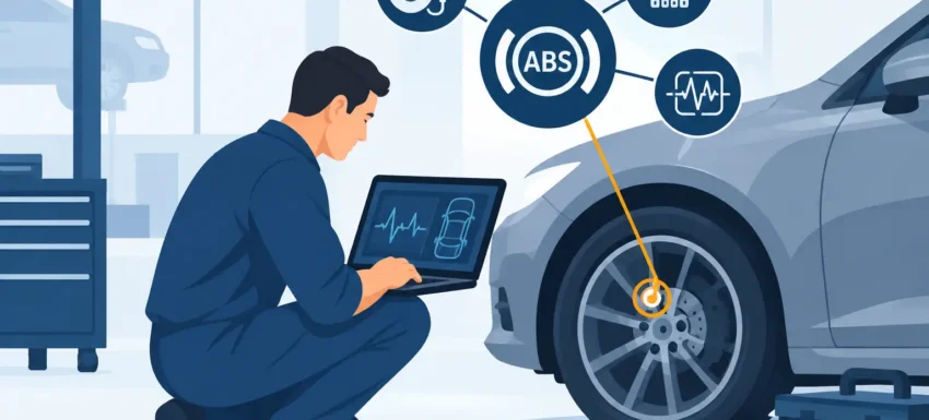
An ABS warning lamp is not a parts-ordering instruction. A proper ABS fault investigation identifies whether the issue sits with a wheel speed signal, damaged wiring, a reluctor ring, low system voltage, a control module or the hydraulic unit itself. Getting that order right prevents repeat bookings, unnecessary sensor replacement and a vehicle leaving the workshop with the underlying fault still present.
For independent garages and capable DIY users, the priority is simple: use live data and measured evidence before fitting parts. Modern braking systems can store a useful fault code, but the code is the starting point, not the diagnosis.
Start an ABS Fault Investigation With the Right Scan Tool
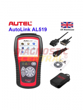
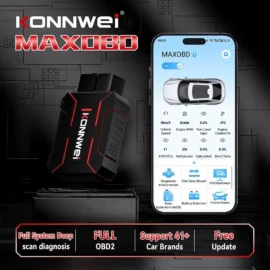
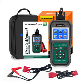
A basic engine-code reader may not communicate with the ABS control unit. That is a common reason for wasted time. The diagnostic tool must support the vehicle’s brake electronics and, ideally, provide manufacturer-specific codes, live wheel speed data, actuator tests and code descriptions.
Begin with a full vehicle scan. Record every stored, pending and historic code before clearing anything. ABS faults can be triggered by low battery voltage, charging faults or network communication issues, so engine, body and gateway modules may provide useful context even when the warning lamp relates to braking.
Pay attention to the wording and status of each fault. “Wheel speed sensor circuit open” points you in a different direction from “implausible signal” or “hydraulic pump motor fault”. Also check whether the code returns immediately with the ignition on, only once the vehicle moves, or after the brake pedal is applied. That timing narrows the test plan quickly.
Clearing codes before recording them removes evidence. It can also turn an intermittent concern into a longer diagnosis, particularly when a wiring fault appears only with suspension movement or moisture.
Check voltage before chasing signals
Low voltage is a regular cause of misleading ABS and stability-control faults. Test battery condition, terminal security and charging voltage before committing to sensor or module work. A weak battery may cause multiple warning lamps at start-up, while poor earth connections can corrupt a sensor reference or module supply.
On a vehicle with several unrelated communication or voltage codes, correct the power supply issue first. Do not assume a long list of faults means every component has failed.
Use Live Data to Find the Bad Wheel Signal
Live wheel speed data is often the fastest route through an ABS diagnosis. Raise the vehicle safely where appropriate, follow workshop lifting procedures, then compare the reported speed from all four wheels. A road test with a second person operating the scan tool can be more revealing where the fault appears only under load, although this must be carried out safely and legally.
At low speed, all wheel readings should rise smoothly and remain credible against one another. A sensor that drops to zero, jumps erratically or reports a noticeably different speed from the others has identified the corner requiring closer inspection. But it has not automatically condemned the sensor.
The fault may be caused by a cracked magnetic encoder ring in the wheel bearing, corrosion lifting a sensor away from its target, excessive wheel-bearing play, contamination, a damaged harness or a poor connector terminal. On many newer vehicles, the encoder is integrated into the bearing seal rather than a visible toothed ring. Fitting a sensor when the magnetic ring is damaged will not fix it.
A useful rule is this: inspect the signal path as a system. The sensor, target ring, air gap, connector, wiring and mechanical condition all matter.
Sensor type changes the test method
Older passive inductive sensors can often be checked for resistance and AC voltage output while the wheel turns. However, a resistance reading alone is not proof that the sensor is serviceable. A sensor can measure within range on a multimeter and still produce a weak or distorted signal in operation.
Many current vehicles use active Hall-effect or magneto-resistive sensors. These need a suitable supply and usually produce a digital switching signal. Resistance testing can be misleading and may not be recommended by the manufacturer. Use wiring information, a back-probe method that avoids terminal damage, and ideally an oscilloscope when the data points to an intermittent or poor-quality signal.
An oscilloscope earns its place when a vehicle has a repeatable low-speed ABS intervention but no obvious stored code. A damaged encoder ring often creates a regular gap or distortion once per wheel revolution. That evidence is far stronger than replacing components on suspicion.
Inspect Wiring Where It Actually Fails
ABS sensor wiring works in a hard environment. It is exposed to steering movement, suspension travel, road spray, salt, heat and stone damage. The obvious visible section may look sound while the conductor has fractured internally near a flex point.
Inspect the harness from sensor to body connector, concentrating on the sections clipped to the suspension leg, routed behind the wheel arch liner and bent during steering. Look for stretched wiring, rubbed insulation, green corrosion in terminals and connectors not fully locked into place. On commercial vehicles and trailers, also inspect adapters, external connections and harness sections exposed to weather and coupling movement.
A wiggle test can help, but make it controlled. Monitor live data or a meter reading while moving the loom gently. If the signal drops out as the cable is flexed, repair the harness correctly rather than twisting wires together and covering them with tape. A sealed repair using the correct cable and connection method is the difference between a lasting repair and a return visit after the next wet week.
Continuity testing is useful, but do not stop there. A wire can show continuity with no load yet fail when vibration or current demand is present. Check for excessive resistance, short circuits to earth or supply, and connector pin tension where access allows.
Separate Wheel-Speed Faults From Hydraulic ABS Faults
Not every ABS warning is a wheel sensor issue. Codes relating to pump motors, valve circuits, pressure sensors, accumulator performance or internal control-unit faults require a different approach.
First confirm module supplies, earths and relevant fuses under load. A fuse that looks intact can still have a poor connection, and a corroded earth can create voltage drop when the pump is commanded. Where the scan tool offers actuator tests, use them carefully and follow the vehicle procedure. A commanded pump test can confirm whether the unit operates, but it must be performed with the vehicle secure and with awareness of noise, pressure and moving components.
Brake fluid condition and level also matter. Low fluid may accompany pad wear or a leak, while contaminated fluid can contribute to hydraulic issues over time. However, fluid condition does not explain every ABS code, so avoid broad servicing as a substitute for targeted testing.
If a hydraulic unit, module or brake component has been replaced, the vehicle may require an ABS bleed routine through a compatible diagnostic tool. Conventional pedal bleeding may not remove air trapped within modulator passages. Follow the specified sequence, then confirm pedal feel and warning-lamp operation before road testing.
Know When Coding or Calibration Is Required
Some repairs need more than fitting the physical part. Steering angle sensors may need calibration after alignment work, battery disconnection or module replacement. A new ABS module may require coding, variant configuration or VIN programming. Wheel bearings with integrated magnetic encoders must be fitted in the correct orientation, because installing one backwards can create a permanent no-signal fault.
This is where vehicle coverage matters. A tool that reads generic codes may not provide the service functions needed to complete the repair. For garages handling mixed makes, dependable multi-system diagnostic equipment saves time because it combines code reading with the live data, actuator control and calibration work that modern braking systems demand.
Prove the Repair Before Handing Back the Keys
After the repair, clear faults only once the cause has been corrected. Re-scan the ABS module, verify that live wheel speeds agree, and carry out a controlled road test. Check that the ABS, traction control and stability-control lamps remain off, as these systems share information on many vehicles.
Do not judge success solely by an extinguished lamp in the bay. A fractured wire may pass a static test and fail after a few miles; an encoder fault may appear only at walking pace. Recreating the original conditions is the final proof.
A disciplined ABS diagnosis protects the customer, the workshop and the repair margin. Read the right module, compare real-time data, test the circuit and mechanical target together, then validate the result on the road. That method turns a warning lamp into a clear repair decision rather than an expensive guess.