A scan tool that powers up but cannot connect is not giving you a vague fault – it is giving you a starting point. If you are asking why won’t OBD communicate, resist the temptation to swap scanners immediately. Prove the diagnostic socket has power and earth, identify the vehicle network in use, and establish whether the problem is with the tool, the port or a module on the vehicle.
On a busy ramp, this matters. A no-communication fault can turn a simple warning-light job into lost time, unnecessary parts replacement and a frustrated customer. A disciplined check takes minutes and prevents guesswork.
Why Won’t OBD Communicate? Start at the Socket
The 16-pin OBD diagnostic connector is usually below the steering column, but its position varies. Before testing electrical values, inspect it properly. Look for pushed-back terminals, green corrosion, damaged plastic, evidence of an aftermarket tracker or insurance device, and signs that someone has forced a plug into the socket.
Pin 16 should have battery positive supply. Pins 4 and 5 are the standard chassis and signal earths. On most modern vehicles, pins 6 and 14 carry CAN High and CAN Low. Older vehicles may use other pins for K-line, manufacturer-specific communication or legacy protocols.
Use a multimeter rather than relying on the scanner’s power light. With the ignition off, pin 16 should normally show close to battery voltage against pins 4 or 5. Then check the earths under load where possible. A weak or high-resistance earth can show an acceptable voltage with a meter but fail when the scan tool attempts to communicate.
If there is no supply at pin 16, check the relevant fuse first. The OBD socket is often fed by the same circuit as the cigar lighter or 12V accessory outlet. A blown fuse caused by a mobile phone charger, coin or damaged accessory socket can remove diagnostic-port power while the rest of the vehicle appears normal. Do not assume the fuse will be labelled “OBD” in the handbook – it often will not be.
Check the Vehicle Battery Before Blaming the Scanner
Low voltage causes more diagnostic trouble than many technicians expect. Modern control units can wake up, shut down and lose network stability when battery voltage is poor. The dash may illuminate normally, yet individual modules may refuse a diagnostic session.
As a guide, a rested battery near 12.6V is healthy. At around 12.2V, it is significantly discharged; below that, communication faults become increasingly credible. Voltage during ignition-on and cranking matters just as much. A battery with a weak cell or poor terminal connection may collapse under load and create a string of misleading network and module codes.
Use a proper battery tester if there is any doubt. On vehicles being programmed, coded or subjected to lengthy diagnostic work, stabilised power support is not optional. It protects modules and stops voltage-related interruptions being mistaken for a deeper electronic defect.
Confirm the Scan Tool Can Actually Cover the Vehicle
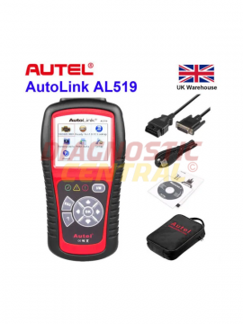
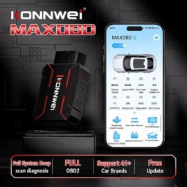
Not every reader that fits the socket can perform the same job. A basic OBD2 code reader may access engine emissions data but fail to enter ABS, airbag, body, transmission or service systems. That is a limitation of the tool’s coverage, not necessarily a vehicle fault.
This is particularly relevant on UK-market vehicles with manufacturer-specific diagnostics, newer CAN FD systems, secure gateways and commercial vehicles. A generic reader may report “link error” or “no communication” when it has reached a system it does not support. Some vehicles also require the ignition in a specific position, the engine stopped, or a manual selection of make, model and system before a session can begin.
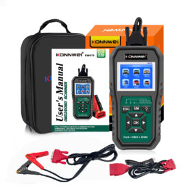
Check the scanner against the exact vehicle, including year, engine and system required. A capable multi-system diagnostic tool saves time because it can interrogate more than the engine ECU. However, capability still depends on software coverage and the correct lead or adapter where applicable. Lorry, trailer and 12V passenger-car connectors are not interchangeable simply because they look similar at a glance.
If the same scan tool communicates correctly with another compatible vehicle, the odds shift towards the car. If several known-good tools fail on one vehicle, stop treating it as a scanner issue and test the network.
Test CAN Bus Health When OBD Will Not Communicate
On most modern vehicles, the diagnostic connector reaches the control units through the CAN network, often via a gateway module. A fault on that network can prevent all-system communication or isolate selected modules.
With the ignition off, vehicle asleep where possible and the battery in sound condition, measure resistance between pins 6 and 14. A healthy terminated high-speed CAN network will commonly measure approximately 60 ohms. This reflects two 120-ohm termination resistors in parallel.
A reading close to 120 ohms can indicate one missing termination path, an open circuit or a disconnected section of the network. Very low resistance suggests a short or multiple terminations. An open circuit reading points to a break, connector problem or incorrect pin allocation for the vehicle being tested. These readings are clues, not a final diagnosis – network design varies, and some vehicles use gateways that alter what you see at the OBD port.
For a clearer picture, use an oscilloscope. A working high-speed CAN pair should show two opposing signals around a 2.5V bias point when data is active. A flat line, a line held high or low, excessive noise, or mismatched waveform shapes directs you towards wiring, a connector or a module pulling the bus down.
Do not unplug modules at random on a live vehicle network. Isolate circuits methodically, follow the wiring information and switch the ignition off before disconnecting controllers. Water ingress in a footwell, corroded loom joints, accident damage and rodent damage are common causes. So are aftermarket alarms, trackers, audio equipment and poorly installed dash cameras tapped into CAN wiring.
Gateway, Security and Module Faults
Many newer vehicles route diagnostics through a central gateway, body control module or security gateway. If that module has no power, poor earth, internal failure or water damage, a scanner may not see multiple systems even though individual ECUs are functional.
A secure gateway is different from a total communications failure. The tool may connect to the vehicle and identify it, but block functions such as clearing codes, active tests, coding or bi-directional control. In that case, the correct route is authorised access and compatible diagnostic equipment, not attempts to bypass vehicle security.
A single failed module can also bring down a shared network. Common suspects depend on the vehicle, but electric power steering modules, ABS units, infotainment systems, door modules and transmission controllers are all capable of causing trouble when internally shorted or flooded. The repair process is about narrowing the network branch and proving the fault, not replacing the most expensive module first.
A Fast Workshop Order of Checks
When a vehicle presents with no OBD communication, use a consistent order. It is faster than chasing codes that you cannot reliably retrieve:
- Check battery condition, terminal security and main earth straps.
- Inspect the 16-pin socket and verify battery supply on pin 16.
- Test pins 4 and 5 for a reliable earth, then inspect the relevant accessory or diagnostic fuse circuit.
- Confirm ignition position, tool software, vehicle coverage and any required adapter lead.
- Try a known-good compatible diagnostic tool before condemning the original unit.
- Test CAN resistance and investigate network voltage or waveform faults where the vehicle design supports it.
- Use wiring data to check gateway supplies, earths and network branches before isolating suspect modules.
This sequence is deliberately basic at the beginning. It catches the failures that waste the most time: blown accessory fuses, low batteries, bent socket pins and a reader being used outside its supported function.
When the Fault Is Intermittent
Intermittent communication faults need evidence. Record battery voltage, outside temperature, moisture conditions, which modules are unavailable and whether the failure occurs with ignition on, engine running or after the vehicle has gone to sleep. A fault that appears after rain points you towards ingress. One that begins during steering movement may indicate a loom issue. One that occurs after fitting accessories deserves a close look at the installation.
Avoid clearing codes or disconnecting the battery before capturing a full vehicle scan if communication is available even briefly. Stored undervoltage, gateway and network codes can establish a direction. They may not identify the failed part, but they prevent the diagnostic process starting blind.
The right diagnostic equipment is only part of the answer. Diagnostic Central focuses on tools that give workshops and capable vehicle owners clear, actionable information, but the tool still needs a sound power supply, a healthy network and correct vehicle coverage to do its job.
Treat no communication as an electrical diagnosis, not a reason to guess. Start at the socket, prove each basic condition, and let the measurements lead you to the fault.