A scan tool that reports an ECU communication failure is not telling you that the ECU has definitely failed. It is telling you that the diagnostic tester cannot establish the expected conversation with one or more control modules. On a modern vehicle, that conversation depends on stable voltage, sound earths, intact wiring, correct network signals and a compatible diagnostic tool. Miss any one of them and the fault-finding process can head in the wrong direction quickly.
For a busy workshop, the priority is to separate a genuine module fault from a power supply, network or diagnostic access issue before fitting expensive parts. For a competent DIY user, the same approach prevents guesswork and avoids condemning an ECU when the real problem is a blown fuse, corroded connector or flat battery.
What an ECU communication failure actually means
Electronic control units do not work in isolation. The engine ECU exchanges information with the ABS, body control module, instrument cluster, transmission controller, airbag system and other modules through vehicle networks, most commonly CAN bus. Your diagnostic scanner reaches these systems through the OBD port or, on some vehicles, through a manufacturer-specific connection path.
A communication fault may appear as a U-code, such as U0100 for lost communication with the engine control module, although code definitions vary by manufacturer. The scan tool may also display messages such as “no communication”, “module not responding” or “unable to connect”. These messages are a starting point, not a diagnosis.
The pattern matters. If the scanner cannot communicate with any module, suspect the vehicle power supply, OBD socket supply, diagnostic connector, main network or scanner setup first. If it communicates with most modules but not one, focus on that module’s feeds, earths, connectors and network branch. A module that disappears intermittently after rain, vibration or a battery change needs a different line of investigation from one that is permanently offline.
Common causes of ECU communication failure
Low voltage and poor power supplies
Modern electronics are highly sensitive to voltage. A tired battery can still crank an engine yet drop below the level needed for modules to initialise properly. Low voltage during starting, jump-starting or programming can create multiple communication codes at once, often alongside implausible sensor faults.
Start with battery condition and charging voltage rather than relying on a dashboard warning alone. Check the battery at rest, monitor voltage during cranking and confirm alternator output. A proper battery tester gives more useful information than a basic voltage reading because it assesses available starting performance as well as state of charge.
Then check the ECU’s individual power feeds. Many vehicles use separate permanent live, ignition live and relay-controlled supplies. A healthy battery does not prove that power is reaching the module. Inspect the relevant fuses under load where possible, verify relay operation and check voltage at the ECU connector against reliable wiring information.
Corroded earth points and damaged connectors
Earth faults cause some of the most misleading electrical symptoms in a workshop. High resistance at an engine bay earth strap, battery terminal, chassis point or module earth can leave an ECU partly powered but unstable. The result may be no-start conditions, random warning lamps, intermittent communication and fault codes across unrelated systems.
Visual inspection is useful, but it is not enough. A connection can look clean while failing under current load. Check for looseness, green corrosion, water entry, damaged terminals and previous repair work. Where appropriate, carry out a voltage-drop test while the circuit is loaded. This is more reliable than simply checking continuity with a multimeter.
Water ingress deserves particular attention. Plenum chambers, scuttle drains, door seals and damaged wiring grommets can allow moisture into modules or connector housings. If the fault follows wet weather, inspect for damp carpets, oxidised pins and signs of previous flooding before replacing anything.
CAN bus wiring faults
CAN bus systems normally use a twisted pair of wires to resist electrical interference. A short to power, short to earth, open circuit, crushed section of loom or poor aftermarket joint can stop multiple modules communicating. Collision repairs, rodent damage, towbar installations, alarm systems and stereo wiring are regular sources of network problems.
A full network failure can often be identified by checking which modules are visible on a capable scan tool. If several units on the same network are missing, identify their common wiring route, power feed or gateway module. Do not start unplugging controllers at random. Removing a module can alter the network condition and make an intermittent fault appear to vanish temporarily.
With the ignition off and the system allowed to shut down, a resistance check across the CAN high and CAN low circuits may indicate whether both terminating resistors are present. Around 60 ohms is common on a healthy terminated high-speed network, but the exact procedure and expected result depend on the vehicle architecture. Follow manufacturer data and avoid probing circuits blindly.
A failed module or incorrect coding
Control modules do fail. Internal water damage, reverse-polarity jump-starting, overheating, poor-quality remapping and component failure can make an ECU unresponsive. Yet a replacement is rarely plug-and-play. Many ECUs require coding, immobiliser matching, software programming or configuration before the vehicle will start and communicate correctly.
A recently fitted module is therefore a major clue. Confirm the part number, vehicle application, software level and coding status. A used unit may be physically identical but incompatible with the vehicle’s specification. Likewise, a module can appear dead after programming if the process was interrupted by low voltage or an unsuitable tool.
A practical diagnostic sequence
The fastest route is a disciplined process, not immediate ECU replacement. Begin by confirming the complaint. Record every fault code, including pending and historic entries, and note which modules your scanner can access. Clear nothing until you have captured the initial evidence.
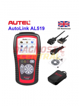
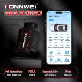
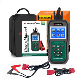
Next, assess battery condition, terminal security and charging voltage. Check the OBD port has its expected power and earth supply, as a dead diagnostic socket can look exactly like a vehicle-wide communication problem. Confirm that the scanner supports the make, model, year and system you are trying to access. Basic code readers are useful for generic engine faults, but they may not enter manufacturer-specific modules or read network data in enough depth.
After the basic checks, inspect fuses, relays, ECU connectors and known earth points. Use wiring diagrams to identify the correct circuits. Check supplies and earths at the affected module before testing network wires. This order matters: testing CAN signals at a module with no proper power supply wastes time.
If the vehicle has a wider network fault, a scan tool with full-system coverage becomes far more valuable than a generic reader. Look at the complete module scan, gateway data and communication topology if supported. An oscilloscope is the right tool where waveform quality needs checking, especially with intermittent CAN faults. A multimeter can identify some opens, shorts and resistance issues, but it cannot show every network fault.
When an issue appears intermittent, use the evidence. Does communication fail only with the engine running, after the vehicle is warm, when the steering is moved or when a particular accessory is used? A careful wiggle test of accessible looms and connectors can expose a weak connection, but keep clear of moving components and never force pins with unsuitable probes.
Avoid the expensive mistakes
The biggest mistake is treating a communication code as a module replacement instruction. ECUs are costly, may need programming and can create immobiliser complications when fitted incorrectly. Prove power, earth and network integrity first.
The second is using an unsuitable scanner and assuming the vehicle is at fault. Tool coverage varies significantly. A reader that only accesses generic OBD2 emissions data cannot reliably diagnose every body, chassis, transmission or commercial vehicle system. Match the diagnostic equipment to the job, particularly where lorries, trailers, older vehicles or brand-specific systems are involved.
Finally, do not overlook the original cause. If an ECU has genuinely failed because water reached its housing, a replacement will be at risk until the leak is repaired. If the fault followed a depleted battery, find out why the battery discharged rather than simply clearing the codes.
A methodical test process turns an ECU communication problem from an expensive unknown into a set of measurable checks. Start with voltage, supplies and earths, establish exactly which modules are missing, then test the network with the right equipment and vehicle data. That approach protects both repair time and the parts budget – and gives you a result you can stand behind.