A vehicle that will not crank, cranks slowly or repeatedly shows a battery warning lamp can waste valuable workshop time when the fault is approached as a simple ‘flat battery’. This starter and charging system guide sets out a more reliable process: prove battery condition first, check cable integrity, test starter circuit voltage drop, then confirm alternator output under realistic load.
Quick answer
- A battery can show 12V at rest yet fail when asked to supply cranking current.
- A charging voltage reading alone does not prove the alternator and its control circuit are healthy.
- Excessive resistance in an earth strap, positive cable or terminal can imitate a failed starter or weak battery.
- Scan for fault codes and live data where supported, particularly on stop-start, smart-charging and battery-monitoring systems.
How the starter and charging system works
The battery supplies high current to the starter motor. When the ignition or start button is operated, the starter control circuit energises the solenoid, which engages the pinion with the flywheel and connects battery power to the motor. Once the engine runs, the alternator replenishes the battery and supplies the vehicle’s electrical demand.
That basic arrangement is familiar, but modern vehicles complicate it. The engine ECU, body control module, immobiliser, battery monitoring sensor and intelligent alternator regulator may all influence whether the engine is permitted to crank and how the alternator charges. A vehicle may therefore have a mechanically sound starter and alternator while still suffering a control, communication or coding issue.
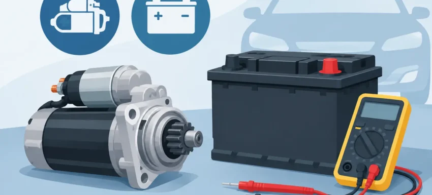
Treat the system as three connected areas: battery condition, high-current cables and connections, and starter or alternator operation. Testing them in that order prevents unnecessary parts replacement.
Start with battery condition, not battery voltage
A resting battery voltage is a useful first check, but it is not a battery test. A fully charged conventional 12V lead-acid battery will commonly settle around 12.6V after resting. At roughly 12.2V it is significantly discharged. However, surface charge, recent driving and temperature can all alter the figure.
Inspect the battery before connecting test equipment. Look for loose terminals, white or blue-green corrosion, damaged clamps, a swollen case, electrolyte leakage and insecure hold-downs. On stop-start vehicles, also confirm that the correct battery technology is fitted. An AGM or EFB battery replaced with an unsuitable standard flooded type may create repeat charging and start-stop complaints.
A dedicated battery tester is more useful than a multimeter because it assesses available cranking performance and internal resistance or conductance. Enter the battery’s stated rating accurately, including whether the label uses EN, SAE or another standard. Test with the battery reasonably charged where possible. A result calling for recharge and retest is not the same as a confirmed failed battery.
For a no-crank complaint, observe voltage during cranking. A substantial collapse suggests a discharged or failing battery, excessive starter draw, or resistance in the circuit. There is no single pass or fail figure for every vehicle and temperature, but a battery falling well below approximately 9.6V during a normal crank attempt warrants investigation.
Check voltage drop before condemning the starter
High-current circuit resistance is one of the most missed causes of slow cranking. A cable can look sound externally while corrosion has travelled under the insulation or a crimp has deteriorated internally. Measuring voltage drop while the circuit is loaded finds this far better than checking continuity with the engine switched off.
Test the positive side by placing the meter between the battery positive post itself, not the terminal clamp, and the starter motor main supply terminal. Crank the engine and record the voltage. Then test the earth side from the starter casing or engine block to the battery negative post. Excessive readings point towards the section of circuit being tested.
As a working guide, each side should generally show only a small drop under cranking load. Around 0.5V or more on one side is reason to inspect connections, cable condition and earth straps closely, although the exact acceptable figure depends on cable length, starter current and vehicle design. Move one meter lead along the circuit to isolate whether the loss is at a terminal, fuse link, cable or engine-to-body earth strap.
Do not overlook the battery terminal connection itself. A clamp can be tight on the post but have corrosion between the metal surfaces. Clean and secure it correctly before repeating the test.
When the starter control circuit is the issue
If battery condition and main cable voltage drops are acceptable, check whether the starter solenoid receives a start command. Depending on design, this may be a switched 12V feed, a relay-controlled circuit or a module command. Use the wiring information for the exact vehicle rather than assuming terminal layout.
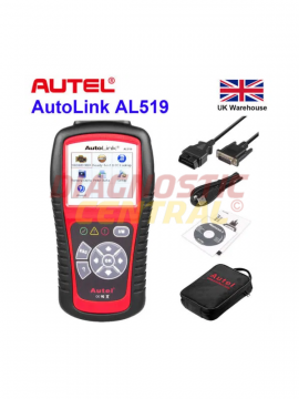
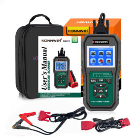
No control signal can be caused by a clutch or neutral safety switch, brake pedal switch, starter relay, immobiliser authorisation fault, key recognition issue or module communication fault. An OBD2 diagnostic scanner with manufacturer-level coverage can be valuable here, where supported, because it may show start authorisation status, relevant fault codes and live data from the engine or body module.
If a proper command reaches the solenoid, cable losses are low and the engine is known to turn freely, a starter motor fault becomes much more likely. Listen carefully: a single click, rapid relay clicking, a spinning motor with no engagement and a heavy slow crank point to different fault paths.
Test alternator output under load
With the engine running, measure voltage directly at the battery posts. Many conventional systems charge in the region of 13.8V to 14.7V, but that range is not a universal rule. Smart-charging systems may intentionally reduce alternator output after starting, raise it during deceleration, or vary voltage according to battery temperature and state of charge.
Start by checking the drive belt, tensioner, alternator connections and battery sensor wiring. A slipping belt, damaged pulley or loose B+ connection can produce intermittent charging faults that a static voltage check misses. Then compare alternator output at idle and at an increased engine speed, first with electrical loads off and then with headlights, heated rear window and blower motor operating.
A low reading with high load may indicate an alternator, regulator, wiring or belt problem. An abnormally high reading can point to a regulator or sensing fault and risks battery damage. On an intelligent system, scan data may show commanded generator duty, battery current, battery temperature and battery sensor faults, making the diagnosis more precise.
An AC ripple check can also help identify failed alternator diodes. Excessive ripple may cause charging concerns, battery drain, electrical interference or warning lamps. The right method and acceptable reading depend on the meter and vehicle, so use a quality meter or oscilloscope where the fault is intermittent or the result is unclear.
Battery replacement may need registration
Many newer vehicles require the replacement battery to be registered, adapted or coded through diagnostics. This tells the energy management system that a new battery has been fitted and, on some models, records its capacity and technology. Skipping this procedure may shorten battery life or prevent the charging system from using the correct strategy.
Check the exact vehicle, model year and battery management system before promising this function. A basic code reader may read engine faults but not access the body module or service function required for battery registration.
For routine assessment, a battery tester is the fastest way to establish whether the battery deserves further charging or replacement. For control-system faults and battery adaptation, choose a diagnostic tool with confirmed coverage for the vehicle and required functions. A multimeter remains essential for voltage-drop work, but it cannot show module authorisation or alternator control data.
FAQs
Can an alternator charge a completely flat battery?
It can restore some charge after the engine has been started, but it is not designed to recover a deeply discharged battery quickly. Charge the battery with a suitable charger first, then test it. Forcing an alternator to replenish a severely flat battery can put it under unnecessary strain.
Why does the battery warning lamp come on after fitting a new battery?
The cause may be a charging-system fault, poor terminal connection, damaged battery sensor wiring or a battery registration requirement. Do not assume the new battery is faulty without testing alternator output and scanning the relevant modules.
Can a bad earth strap stop a car starting?
Yes. A corroded or loose engine earth can restrict starter current and cause slow cranking, clicking, warning lamps or erratic electronic behaviour. A loaded voltage-drop test is the correct way to assess it.
Why does my vehicle start after a jump start but then fail again?
The original battery may be discharged or failing, the alternator may not be charging properly, or there may be a parasitic drain. Test battery health and charging performance before fitting parts.
Accurate electrical diagnosis comes from proving each part of the circuit under load, not from replacing the first component that looks suspicious. If you need help selecting suitable test equipment, contact Diagnostic Central with the registration, VIN and the functions you need to perform, so the vehicle coverage can be checked before you buy.