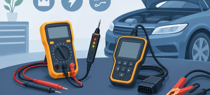
A warning lamp and a stored fault code are only the start of a diagnosis. The essential vehicle electrical testing tools in a proper workshop tell you whether the circuit has power, earth, continuity, signal quality and current flow. Without that evidence, replacing a sensor, relay or control unit is often an expensive guess.
Modern cars and vans rely on networks of modules, low-current reference circuits and electronically controlled loads. A basic tool kit can still solve plenty of faults, but the tools must suit the job and be used in the right order. Start with battery condition and supply voltage, then prove the circuit before condemning a component.
Essential vehicle electrical testing tools for fault finding
A quality digital multimeter
A digital multimeter is the foundation of electrical diagnosis. It measures DC voltage, resistance, continuity and, on better units, frequency, duty cycle and diode function. For daily vehicle work, choose a meter with a clear display, fused current inputs, reliable probes and an automotive-friendly voltage range.
Voltage testing is where a multimeter earns its place. It can confirm battery voltage, check an ignition feed, verify a sensor reference supply or reveal a poor earth connection. Resistance and continuity modes are useful, but only on an isolated circuit. Never measure resistance on a live circuit, and do not trust a continuity beep as proof that a wire can carry load.
That last point matters. A corroded cable can show continuity yet fail as soon as a fuel pump, cooling fan or heated screen demands current. A voltage-drop test across the positive or earth side of the circuit is the more decisive check. With the component operating, even a small unexpected voltage drop can expose resistance that a static test misses.
A battery tester and charging-system tester
Many apparent electrical faults begin with low system voltage. Modules may log communication faults, starters may turn slowly and stop-start systems may become unavailable because the battery is weak, undercharged or incorrectly registered after replacement.
A dedicated battery tester assesses the battery’s available cranking performance rather than simply reporting open-circuit voltage. That distinction is critical. A battery can show more than 12V at rest and still collapse under load. A capable tester should also assess alternator charging voltage and, where supported, ripple and charging performance.
For garages handling modern vehicles, battery technology support matters. AGM and EFB batteries behave differently from conventional flooded types, and testing against the correct battery standard and rated cold cranking figure produces a result you can act on. Check the battery terminals and main earth straps at the same time. A good battery tester cannot compensate for a loose, oxidised connection.
A test light, used with judgement
A test light remains one of the quickest ways to establish whether a supply is present, particularly on lighting, relay and basic accessory circuits. An incandescent test lamp places a modest load on the circuit, which can make it more revealing than a high-impedance meter when a connection is weak.
It is not the right tool for every circuit. Do not use a conventional test light on airbag wiring, CAN lines, ECU sensor feeds or low-current module outputs. The risk is not worth it. An LED test light reduces circuit loading, but it also may not expose high resistance as effectively. Keep both the application and the circuit design in mind.
Power probes and circuit testers
A powered circuit tester speeds up diagnosis when used by someone who understands the wiring diagram. It can display voltage and polarity, check continuity and apply power or earth to a component. That makes it useful for testing motors, lamps, relays, solenoids and certain actuators without building temporary jumper leads.
The trade-off is obvious: applying power to the wrong terminal can damage a control module or trigger an unwanted function. Use fused leads, identify the circuit first and avoid commanding electronic circuits blindly. This is a productive workshop tool, not a substitute for circuit knowledge.
Tools that turn a reading into a diagnosis
Back-probe pins, fused leads and breakout accessories
The best meter is limited by poor connection at the test point. Back-probe pins allow measurements from the rear of a connector while it remains connected and operating. This is essential for checking sensors and actuators under real conditions, rather than testing an unplugged circuit that behaves differently.
Use fine, insulated back-probes that do not spread terminals or pierce seals. Piercing wire insulation should be a last resort because it creates a route for moisture and corrosion. Fused jumper leads, crocodile clips and terminal test leads also save time, provided they are rated for the work and used neatly.
For trailers, commercial vehicles and workshop fleets, dedicated socket testers and adapter cables are equally valuable. They make it possible to isolate a vehicle-side, trailer-side or adapter fault quickly instead of chasing lamps and connections one by one.
Current clamp meter
A current clamp measures current without disconnecting the circuit, making it one of the most useful tools for higher-level electrical diagnosis. Clamp it around a single conductor to assess starter draw, alternator output, glow plug operation, fuel-pump current or parasitic battery drain.
Current patterns often reveal faults that voltage tests cannot. A starter pulling excessive current may point to mechanical drag or an internal starter issue. A pump with a rising or unstable current draw can indicate wear before it fails completely. For parasitic drain testing, select a low-current clamp with suitable resolution. A standard high-current clamp may not reliably show the small draw that flattens a battery over several days.
Automotive oscilloscope
An oscilloscope is not essential for every DIY repair, but it is a serious advantage for professional diagnostics. It shows how a signal changes over time, allowing you to see crankshaft and camshaft sensor waveforms, injector control, ignition events, CAN communication and alternator ripple.
A multimeter may report that a sensor has voltage. A scope can show whether the waveform is distorted, intermittent or out of synchronisation. That is the difference between replacing a perfectly good sensor and proving a wiring, timing or reluctor-ring issue.
Scope work has a learning curve. You need correct probe connections, a known-good pattern where possible and an understanding of what the ECU expects. For workshops regularly dealing with no-starts, network faults and intermittent running problems, that investment pays back quickly.
Diagnostic scanner
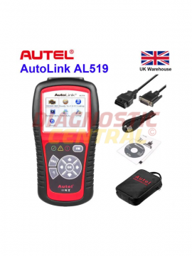
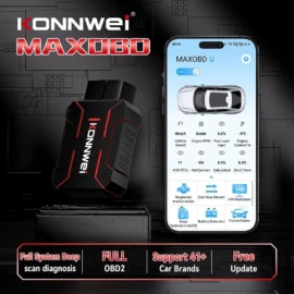
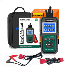
An OBD2 scanner is not an electrical test tool in the traditional sense, but it belongs beside the meter. It reads fault codes, live data, freeze-frame information and, depending on capability, module data and bidirectional tests. The scanner tells you what the vehicle has detected. Electrical tools prove why it detected it.
Use live data to target testing. If a scan tool reports an implausible coolant temperature, check the sensor’s reference voltage, earth and signal at the connector before fitting parts. If an actuator test commands a cooling fan, measure the supply and current while the command is active. Combining scan data with physical measurement is faster than treating either tool as a complete answer.
A practical testing order that avoids wasted parts
Electrical diagnosis is most efficient when the basic checks are not skipped. A sensible order is to confirm the complaint, scan all relevant modules, assess battery and charging condition, inspect connectors and wiring, then test supply, earth and signal under load. Only after those checks should component replacement become the likely next step.
Do not overlook the simple causes. Water ingress in a connector, a rubbed-through loom near a hinge, a blown fuse caused by a seized motor or an earth point hidden under corrosion can create faults that look far more complex on the scanner. The fault code may name a circuit or system, not the failed part.
Wiring diagrams are part of the tool kit too. They show splice points, fuse locations, connector pin numbers and shared supplies. Testing a wire from end to end without understanding what else is connected to it can lead to false readings or accidental damage.
Choosing tools for your workload
A competent DIY user can cover a great deal with a dependable multimeter, battery tester, safe test light, back-probe set and a vehicle-compatible scanner. That combination is enough to investigate many starting, charging, lighting and sensor supply faults properly.
A busy garage benefits from adding a current clamp, powered circuit tester, quality leads and an automotive oscilloscope. Commercial vehicle work may also demand the correct lorry and trailer adapters, as connector standards and system voltages vary. Buy for the vehicles you actually see, not for a specification sheet full of functions you will never use.
Reliable tools shorten the path from symptom to proof, but method still matters most. Establish the power supply, prove the earth, test the circuit under its normal load and use scan data to support the result. That approach gives customers a repair based on evidence, not a pile of replaced parts.